LiDAR · catenary · thermal
High-voltage power lines
A high-voltage power line is a corridor many kilometres long, with conductors, towers, vegetation and crossings that must be known accurately. Drone LiDAR captures the whole corridor in a classified point cloud, from which the actual catenary, the clearances and the digital terrain model (DTM) of the route are derived.
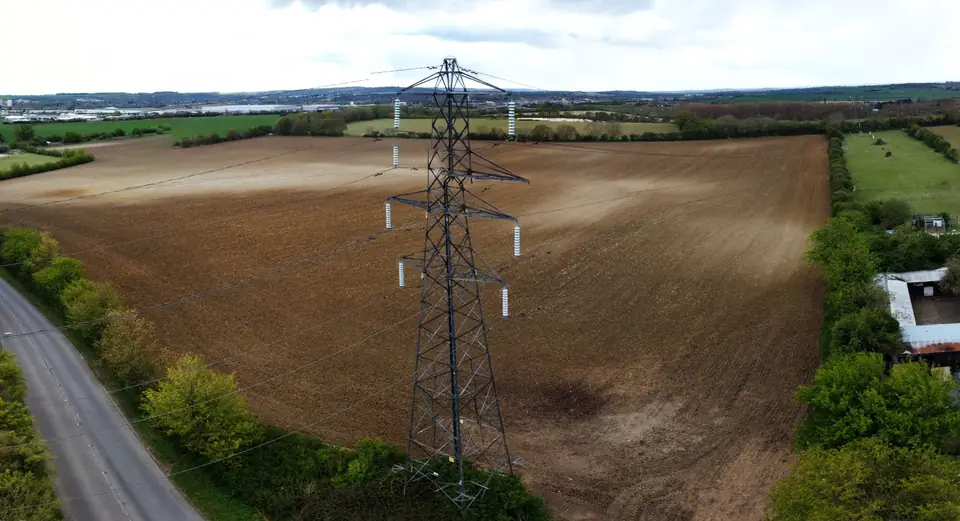
A long corridor with many elements to measure
Power lines cross all kinds of terrain, often with dense vegetation and difficult access. Measuring towers, conductor sag and clearances to trees on foot is slow and requires outages or work at height. And vegetation grows: the safety clearance today is not the one next year.
Drone LiDAR solves both problems. It captures conductors, towers, vegetation and terrain at the same time, without touching the line and without interrupting supply. And it leaves a dated record that can be repeated to follow how the corridor changes.
What we capture on a high-voltage power line
We fly the corridor with LiDAR, which records several returns per pulse: it detects thin conductors and vegetation, and multiple returns help record the ground through gaps in the canopy. The cloud is classified according to the ASPRS standard into conductors, towers, vegetation by height, buildings and ground, and we check the coverage of the ground points, which can be sparse under very dense vegetation. With GNSS RTK we set control points along the route.
The metric RGB camera provides the orthophoto and detailed photographs of towers and insulators. With the thermal camera we inspect joints, clamps and insulators for hot spots, and locate them in the model.
What we deliver
The classified point cloud of the corridor in LAS or LAZ. The DTM and the longitudinal profile of each span for the mechanical calculations. The actual catenary of each conductor, measured in the conditions at the time of the flight. The clearance analysis of vegetation and obstacles to the conductors, with the areas that breach the safety margin set by the client, in SHP and in a report.
If the line is to be designed or modified, we also deliver the corridor DTM in DWG for line design software and the orthophoto for permitting.
Typical accuracy is 2 to 5 cm, expressed as root mean square error (RMSE) on open ground or well-defined surfaces, in the project reference system (ETRS89 / UTM, with orthometric heights unless another reference is requested). It is checked against independent checkpoints that are not used in the adjustment. It depends on the sensor, the GSD, the ground control and the vegetation. The accuracy for each project is agreed in the proposal and documented in the control report.
How it is used in the project
Maintenance teams prioritise pruning and felling with the map of clearance breaches, instead of walking the whole line. Design engineers use the DTM and span profiles to uprate lines, replace conductors or design new routes. The line model serves as a tower inventory and as a base for comparison with later flights.
Everything can be viewed on our web GIS platform, with the point cloud in a 3D viewer and the alert zones over the orthophoto, so that operations, maintenance and engineering work on the same data.
Where we work
We cover corridors in the Valencia region (Comunitat Valenciana), from the grid connection lines of renewable plants inland in Valencia and Castellón to the distribution networks in Alicante. We also work in the rest of Spain. Flights are planned with the authorisation that each section requires.
Questions about High-voltage power lines
Why LiDAR and not photogrammetry for power lines?
Conductors are too thin for photogrammetry to reconstruct reliably, and under trees it cannot see the ground. LiDAR detects the cables directly, and its multiple returns help record the ground through gaps in the vegetation. We classify the ground points and check the coverage obtained.
Does the line have to be switched off for the flight?
No. The drone flies at a safe distance from the conductors and the capture does not interfere with supply. Each flight is planned in line with drone regulations and the conditions set by the line operator.
What is a clearance analysis?
The distance from each vegetation or building point to the conductors is measured in the classified cloud. Areas below the margin set by the client are marked on the orthophoto and delivered as a list of actions.
Do you deliver the catenary for mechanical calculations?
Yes. The actual geometry of each conductor in each span is extracted from the LiDAR cloud, with the sag under the temperature and load conditions at the time of the flight. It is delivered in DWG and in formats for line design software.
Tell us where the project is and what you need to solve
You can send us the site boundary, a plan or the specification. We will reply within one or two working days to review the scope and confirm when you can expect the proposal.