DWG · DXF · PDF · CSV
Longitudinal profiles and cross-sections
A profile shows how the ground elevation changes along a line. The longitudinal profile follows the alignment; cross-sections cut across it at regular intervals. We generate them from a project-specific digital terrain model (DTM) produced by drone and deliver them in DWG, ready to set the vertical alignment and measure earthworks.
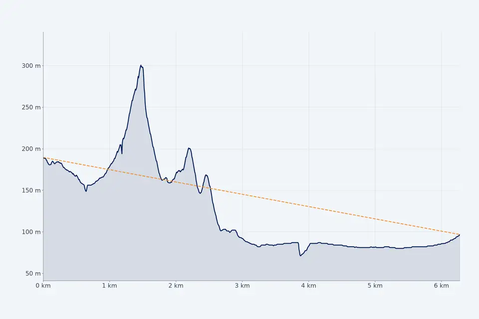
What is a longitudinal profile
The longitudinal profile is the vertical section of the ground along the centreline of a linear project: a road, a railway, a track, a canal or a pipeline. The horizontal axis shows the chainage (distance from the start) and the vertical axis the elevation, usually with the vertical scale exaggerated so that the relief can be read.
The vertical alignment, the line of the finished works, is drawn over the ground profile. The difference between the two at each point shows whether there is cut or fill, and how much. That is why the longitudinal profile is the central document in the design of any alignment.
What are cross-sections
Cross-sections are cuts perpendicular to the centreline, taken at regular intervals (every 10 m, every 20 m) and at key points. They show the shape of the ground on both sides of the alignment and allow the typical section to be drawn: carriageway, hard shoulders, ditches and side slopes.
The cut and fill areas are measured on each cross-section. Multiplying by the distance between sections gives the earthworks volume of the stretch. They are also the basis for checking formation widths, slopes and the land take of the works.
How profiles are obtained from the DTM
First, the corridor is surveyed by drone: LiDAR if there is vegetation or scrub-covered slopes, photogrammetry if the ground is visible. With GNSS RTK control points, a DTM of the corridor is produced with centimetre accuracy. A strip of several tens of metres on each side of the centreline is usually enough.
The centreline is defined in plan on the DTM, with its horizontal alignment. The software extracts the longitudinal profile by sampling elevations along the centreline, and the cross-sections at the specified chainages. Breaklines (carriageway edges, ditches, walls) are added so that the sections capture the real breaks in the ground.
Accuracy and formats
The profiles inherit the accuracy of the DTM. Their typical vertical accuracy is 2 to 5 cm, expressed as root mean square error (RMSE) on open ground, in the project reference system (ETRS89 / UTM, with orthometric heights unless another reference is requested). It is checked against independent checkpoints that are not used in the adjustment. It depends on the sensor, the GSD, the ground control and the vegetation. The accuracy for each project is agreed in the proposal and documented in the control report.
Compared with profiles taken from the MDT05, the 5 m national terrain model of the IGN (National Geographic Institute of Spain), the level of detail is in another league: ditches, kerbs, walls and terraces appear that a 5 m grid does not capture. Where there is coverage, the CNIG publishes finer products such as the MDT02; it is worth comparing their date, resolution and accuracy with what the alignment requires.
We deliver the profiles in DWG or DXF, with elevation and distance bands, in the format read by Civil 3D and other alignment design software; as scaled PDFs for printing; and the elevations in CSV or XLSX for spreadsheets. The DTM and the orthophoto of the corridor always accompany the profiles.
What they are used for: roads, railways and canals
Profiles are needed in any project with a centreline:
- Vertical alignment design for roads, rural tracks and industrial estate roads.
- Railway alignments: study of the corridor ground and formation checks.
- Canals, irrigation channels, sewers and pipelines: gradients and crossing points.
- High-voltage power lines: span profile between towers for the catenary.
- Earthworks measurement from cross-section areas.
- As-built checks against the design.
Questions about Longitudinal profiles and cross-sections
What is a longitudinal profile?
The vertical section of the ground along the centreline of a linear project. It shows the elevation at each chainage and is used to draw the vertical alignment and measure cut and fill.
What is the difference between a longitudinal profile and a cross-section?
The longitudinal profile follows the alignment from start to end. Cross-sections are cuts perpendicular to it, taken at set intervals, that show the ground on both sides and allow the typical section to be drawn.
How often are cross-sections taken?
Every 10 or 20 m is typical, plus key points (changes of gradient, crossings, structures). As they are extracted from a continuous DTM, the interval can be changed without returning to the field.
What is the vertical alignment?
The line that defines the elevation of the finished works along the centreline, also called the grade line. It is drawn over the longitudinal ground profile; the difference between the two at each point is the cut or fill.
What format are the profiles delivered in?
DWG or DXF with elevation and distance bands, ready for Civil 3D and alignment design software, as scaled PDFs and with elevations in CSV or XLSX. Always accompanied by the DTM and the orthophoto of the corridor.
Services that produce it and sectors that use it
Tell us where the project is and what you need to solve
You can send us the site boundary, a plan or the specification. We will reply within one or two working days to review the scope and confirm when you can expect the proposal.