SHP · GPKG · DWG · GeoTIFF
Drainage network and catchments
The drainage network describes where water flows when it rains: valley lines, watercourses and points where flow concentrates. Together with catchments and their divides, it is the basis of flood studies and of drainage design for any development. We calculate it on a project-specific digital terrain model (DTM) produced by drone, showing the real state of the ground.
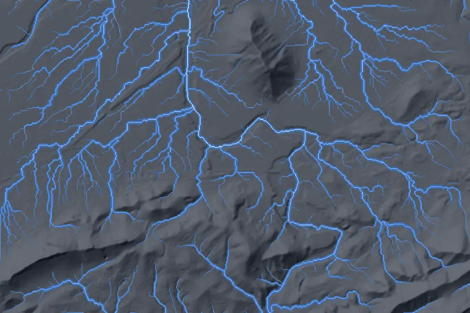
What is a drainage network
The drainage network is the set of lines along which rainwater runs over the ground: from small valley lines to ravines and main watercourses. Each line has an area that drains into it and an order based on how many tributaries it receives.
Divides are the ridge lines that separate two catchments (watersheds): water falling on one side goes to one, and water falling on the other side goes to the other. Valley lines are the low lines where flow concentrates. Between them, they describe the hydrological behaviour of a site.
How it is calculated from the DTM: flow direction and accumulation
Everything starts from the DTM. First, the DTM is corrected to remove artificial depressions (sinks) that would hold water in the calculation. Then the flow direction is determined for each cell: towards which of its neighbours the water runs according to the slope.
The flow directions are used to calculate flow accumulation: how many cells drain to each point. Where accumulation exceeds a threshold, a drainage line appears. From the outlet points, the catchments and sub-catchments are delineated, and from them the divides. The whole process is carried out in GIS on the DTM we survey with LiDAR or photogrammetry.
The quality of the result depends on the DTM. A model with a 5 m grid cannot see a terrace, a ditch or a wall that diverts water. A drone DTM, with centimetre cells, can.
Catchments, divides and valley lines in the project
For each catchment we deliver its area, perimeter, mean slope, main channel length and outlet point. These parameters feed the flow calculations in hydrological and flood studies, and the sizing of ditches, culverts and ponds.
In a solar PV plant, the drainage network shows where not to place modules, where to route access tracks and how to prevent runoff from eroding the piles. On an industrial estate or an urban development, it defines surface drainage and discharge points.
Accuracy and formats
The network and the catchments inherit the accuracy of the DTM. Its typical vertical accuracy is 2 to 5 cm, expressed as root mean square error (RMSE) on open ground, in the project reference system (ETRS89 / UTM, with orthometric heights unless another reference is requested). It is checked against independent checkpoints that are not used in the adjustment. It depends on the sensor, the GSD, the ground control and the vegetation. The accuracy for each project is agreed in the proposal and documented in the control report.
This makes it possible to detect valley lines only a few decimetres deep, which a grid of several metres smooths out. The accumulation threshold is agreed with the client according to the scale of the study.
We deliver the drainage lines, divides and catchment polygons in SHP or GeoPackage with their attributes, in DWG for integration into the project, and the flow direction and accumulation rasters in GeoTIFF. The base DTM and orthophoto accompany the deliverable.
What it is used for: flood studies, solar PV and construction
The drainage network and catchments are used in:
- Flood and hydrological studies: catchment delineation and parameters for flow calculations.
- Solar PV plants: water paths, erosion and drainage design between rows.
- Industrial estates and urban developments: surface drainage, ditches and discharge points.
- Roads and railways: sizing of cross-drainage structures.
- Agriculture: design of terraces, irrigation channels and field drainage.
- Civil works: temporary runoff diversions during construction.
Questions about Drainage network and catchments
What is a drainage network?
The set of lines along which rainwater flows over the ground, from small valley lines to main watercourses. It is calculated on the DTM from flow direction and accumulation.
What are divides and valley lines?
Divides are the ridge lines that separate neighbouring catchments. Valley lines are the low lines where water concentrates. Together they describe how runoff is shared out across a site.
Can it be used for a flood study?
Yes, as a base. We deliver the catchments with their parameters (area, slope, channel length) and the detailed DTM, which the hydrology consultant uses to calculate flows and model water levels.
Why is the official IGN DTM not enough for drainage?
The MDT05, the national DTM of the IGN (National Geographic Institute of Spain), has a 5 m grid that does not capture ditches, terraces, walls or tracks, which are exactly what divert water on a site. Where there is coverage, finer products such as the MDT02 exist, but it is worth comparing their date and detail with what the study requires. A current drone DTM, with centimetre cells, does capture them.
What format are the catchments and drainage network delivered in?
SHP or GeoPackage with attributes, DWG for the project and GeoTIFF for the flow rasters. They open in QGIS, ArcGIS, Civil 3D and the usual hydraulic modelling software.
Services that produce it and sectors that use it
Tell us where the project is and what you need to solve
You can send us the site boundary, a plan or the specification. We will reply within one or two working days to review the scope and confirm when you can expect the proposal.