LiDAR · profiles · DTM · orthophoto
Roads and railways
Linear works require continuous mapping of long corridors: the ground along the route, slopes, drainage structures and crossings. With drone LiDAR and photogrammetry we survey the whole corridor and deliver the digital terrain model (DTM), longitudinal profiles and cross-sections and the orthophoto used by alignment design engineers and site supervision teams.
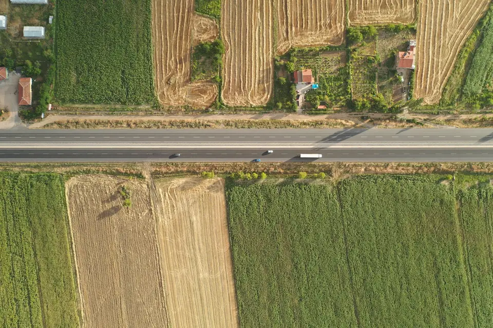
A corridor kilometres long that must be measured in full
A road, bypass, track or railway project needs the ground along the whole centreline and a strip on each side. Surveying it on foot is slow and, on routes in service, means traffic closures and risk to staff. Public data from CNIG (the MDT05 and, depending on coverage, the MDT02 or PNOA-LiDAR point clouds) is useful for preliminary studies and options. It is worth comparing its date, resolution, accuracy and detail with what profiles and volume calculations require: a 5 m grid does not capture a ditch.
The drone covers the corridor in successive flights without affecting traffic. LiDAR helps record vegetated slopes and ditches; photogrammetry provides the orthophoto and the detail of the formation. The result is a continuous DTM of the corridor, with the current date and the control the project requires.
What we capture on a road or railway corridor
LiDAR for slopes, structures and vegetated ground, where multiple returns help record the ground through the gaps and we check the coverage of the ground points; a metric RGB camera for the orthophoto and the formation; GNSS RTK for control points along the route; a total station where millimetre accuracy is needed, as on structures or when tying into existing survey stations.
On routes in service, flights are planned so as not to interfere with traffic or railway operations, and in line with drone regulations. During construction, the flight is repeated by phase to document progress.
What we deliver
The corridor DTM in DWG, with breaklines (carriageway edges, ditches, top and toe of slope), compatible with Civil 3D and alignment design software. The longitudinal profile of the centreline and cross-sections at the interval the project requires, with elevation bands. The corridor orthophoto with a GSD of 2 to 5 cm/px. The classified point cloud in LAS for slopes and structures.
For modification or maintenance projects, the 3D model of bridges, underpasses and walls, and a comparison between dates of slopes at risk of instability.
Typical accuracy is 2 to 5 cm, expressed as root mean square error (RMSE) on open ground or well-defined surfaces, in the project reference system (ETRS89 / UTM, with orthometric heights unless another reference is requested). It is checked against independent checkpoints that are not used in the adjustment. It depends on the sensor, the GSD, the ground control and the vegetation. The accuracy for each project is agreed in the proposal and documented in the control report.
How it is used in the project
Alignment engineers define the centreline and the vertical alignment on the DTM and profiles, and calculate earthworks from the cross-section areas. Site supervision measures earthworks with periodic flights, comparing each state with the previous one or with the design, and checks the as-built works. Maintenance teams use the orthophoto and point cloud as a corridor inventory: signs, barriers, drainage and slopes.
All layers are published on our web GIS platform, so that the design and construction teams consult the same data by chainage.
Where we work
We survey corridors throughout the Valencia region (Comunitat Valenciana), from inland roads and tracks in Valencia to routes in Alicante and Castellón, and in the rest of Spain and Europe. Being based in Xàtiva means we can reach any point in the three provinces within a few hours.
Questions about Roads and railways
How wide a corridor is surveyed?
Whatever the project requires: a strip of several tens of metres on each side of the centreline is typical at design stage, and more for bypasses and junctions. As the whole strip is flown, the area can be extended without returning to the field.
Are the profiles compatible with Civil 3D?
Yes. The DTM is delivered with breaklines in DWG or DXF, so Civil 3D and other alignment design software read it as a surface and generate the profiles along whatever centreline is defined. We also deliver the profiles drawn with elevation bands.
Can you fly over a road that is in service?
Yes, with the planning and authorisations required by drone regulations and by the road owner. The flight does not interfere with traffic and avoids closures and work on foot on the carriageway.
Can it be used to monitor slopes?
Yes. The LiDAR cloud and DTM from each flight are compared with earlier ones to detect movement, rockfalls and erosion on cuttings and embankments, and the changes over time are documented.
Services and products for this sector
Tell us where the project is and what you need to solve
You can send us the site boundary, a plan or the specification. We will reply within one or two working days to review the scope and confirm when you can expect the proposal.