Mapping ·
Solar farm topographic survey: what data to ask for
Topographic survey for solar farms and large sites: which deliverables to request, what resolution each phase needs and how to avoid flying twice.
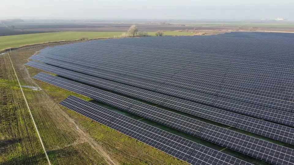
A topographic survey for a solar farm is not a plan with spot heights: it is a set of data the engineering team uses to decide where the structures go, how much earth is moved and where the water runs. The same applies to any development on a large site, whether a wind farm, an industrial estate or a housing development. This article reviews which deliverables are worth requesting, how they are produced with a drone and what resolution and accuracy make sense at each phase.
What engineers need to know about the ground before designing
Whoever designs a solar plant needs to know which areas take the structure without levelling, where earth has to be moved, which areas are shaded, where the water runs and what is already on the site. Each question has a dataset that answers it.
The usual mistake is to ask for “the survey” without specifying which, and to discover at design stage that a layer is missing or that the model does not have the resolution required. Then it is back to the field.
The topographic data for a solar plant, one by one
A bare-earth DTM
The digital terrain model (DTM) is the basis for everything else. It represents the ground elevation without vegetation, buildings or objects. Slopes, contour lines, profiles, drainage and earthworks are all calculated from it.
What matters in a DTM is the ground classification it comes from. With scrub or tall crops, a vegetation point taken as ground appears as a mound that does not exist. It is worth asking how the ground was classified and what ground coverage was checked.
A DSM for shading analysis
The digital surface model (DSM) includes everything on the terrain: trees, buildings, walls, towers. It is the model used to calculate shading, because obstacles are precisely what the DTM removes.
For the shading analysis, what matters is the site and its immediate surroundings: trees along the boundary, a neighbouring warehouse, an embankment. The distant horizon, relief several kilometres away, can be taken from the public models of the IGN (National Geographic Institute of Spain). Detail is needed close by.
Contour lines at the right contour interval
Contour lines are generated from the DTM. The contour interval, the elevation difference between two consecutive contours, is chosen according to the scale of the plan and its use.
- For preliminary studies and general plans, contours every 1 to 5 m are enough to read the relief.
- For design, 0.5 m or 1 m is usual.
- In detailed areas, such as platforms, access roads or a substation, a smaller interval can be requested if the DTM supports it.
A very fine interval on a model that lacks that accuracy only draws noise. A contour is never more accurate than the DTM it comes from.
Slope and aspect
Slope and aspect maps are calculated from the DTM, cell by cell. They are used to mark out the areas suitable for the chosen structure and those that require levelling. The admissible slope limits are set by the manufacturer of the tracker or fixed structure, not by the survey.
Aspect matters too. On a north-facing slope the rows shade each other more, which means spacing them further apart or ruling the area out.
Drainage network and catchments
The drainage network and catchments (watersheds) are calculated from the DTM. They show where water runs, which area drains to each point and where runoff concentrates. With them, the engineering team designs ditches, crossings and erosion protection.
Catchments do not stop at the site boundary: water may come from slopes outside it. The survey has to cover those areas or rely on the public DTM for the rest of the catchment. The hydraulic calculations are done by the engineering team; the survey provides the terrain, the network and the catchments.
Boundary, site limits and existing features
The survey records the physical features that mark the limit (fences, walls, boundary markers, tracks, irrigation channels) and those that constrain the design: buildings, ponds, wells and visible easements. Measuring what is on the ground is not establishing the legal boundary of a property: whether it matches the cadastre and the land registry is a separate matter, and it is better to find out early.
Vegetation, obstacles and existing power lines
Isolated trees, hedges, tree crops that will be removed and power lines crossing the site. The orthophoto shows them; the DSM and the point cloud give their height. With LiDAR, the conductors of a power line are recorded as points.
Coordinate reference system and formats
The reference system has to be set before flying. In Spain the usual choice is ETRS89 with the UTM projection in the relevant zone, and orthometric heights with the official geoid model. If the project uses another reference, it is agreed at the start and recorded in writing.
Formats are requested to suit the engineering software: the DTM in GeoTIFF or as a TIN mesh in LandXML, contours in DWG or SHP, the point cloud in LAS or LAZ and the orthophoto in GeoTIFF.
How a large site is surveyed with a drone
The capture method is chosen to suit the ground, not the other way round.
- Photogrammetry with a metric RGB camera on open ground: stubble, short arable crops, levelled platforms. It produces the orthophoto, with a GSD (ground sampling distance) of 2 to 5 cm/px, and a dense cloud from which a very detailed DTM is derived. The GSD is the image resolution, not the accuracy of the model.
- LiDAR where there are trees, scrub or tall crops. Multiple returns help record the ground through gaps in the vegetation. We classify the ground points and check the coverage obtained, which can be sparse under very dense vegetation.
- Combined, with a LiDAR sensor and an RGB camera at the same time, when the site mixes open and covered areas, or when both the terrain and the orthophoto are needed.
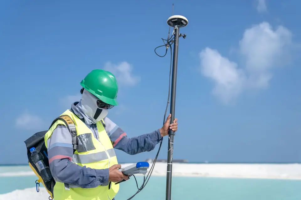
In both cases the drone relies on GNSS RTK and on ground control points (GCPs) measured in the field. Some of the measured points are kept out of the adjustment: these are the independent checkpoints, which measure the real accuracy of the result.
The area covered per day depends on the terrain, the sensor, the requested resolution, the airspace and the planning. We set it in the flight plan for each project.
What resolution and accuracy to ask for at each phase
Not every phase needs the same data. Asking for too much adds cost and file size; asking for too little means repeating the work.
| Phase | Purpose | Usual data | Indicative resolution and accuracy |
|---|---|---|---|
| Preliminary study | Feasibility and options | Public DTM, PNOA orthophoto | 2 to 5 m grid, depending on coverage |
| Design | Layout and quantities | DTM, DSM, contours, drainage, orthophoto | 10 to 20 cm cell; typical RMSE of 2 to 5 cm |
| Setting out and construction | Installation and control | Control network, construction stages | Measured in the field with GNSS RTK or a total station |
For the preliminary study, CNIG publishes the MDT05 for the whole of Spain and, depending on coverage, the MDT02 or the PNOA-LiDAR point clouds (PNOA is Spain’s National Aerial Orthophoto Programme). Once their date, resolution and accuracy have been compared with what the study requires, they are usually enough to rule out sites and compare options.
The design phase needs a survey of its own. Typical accuracy is 2 to 5 cm, expressed as root mean square error (RMSE) on open ground or well-defined surfaces, in the project reference system (ETRS89 / UTM). It is checked against independent checkpoints that are not used in the adjustment. It depends on the sensor, the GSD, the ground control and the vegetation. The accuracy for each project is agreed in the proposal and documented in the control report.
For setting out, the reference is the control network: structures are set out in the field with GNSS RTK or a total station, and monitoring flights record the actual state at each stage for comparison with the previous one or with the design.
How to avoid flying twice
Most repeat flights have the same cause: something that was not defined before flying. A short checklist for the request for proposal:
- Boundary with a margin. Include access roads, the grid connection route if known and the slopes that drain onto the site.
- Capture to suit the vegetation. If there are covered areas, ask for LiDAR from the start. A photogrammetric DTM under trees cannot be fixed in the office.
- A fixed reference. Coordinate system, height model and, if there is one, the project control network.
- Control stations that are kept, to be reused for setting out and for construction flights. That way, successive stages are comparable.
- The classified point cloud as a deliverable. With it, the DTM, the DSM or the contours can be regenerated at another cell size or contour interval without flying again.
- Agreed formats, with a sample beforehand to check that the engineering software reads it without conversion.
What this survey is used for beyond solar
The same dataset serves other developments on large sites: on a wind farm, with the turbine positions, crane platforms and access roads; on an industrial estate or a housing development, as the basis for planning and for the earthworks balance.
We work from our office in Xàtiva, in the Valencia region (Comunitat Valenciana), on projects across Spain and in Europe. The approach is the same: first define what the engineering team needs to resolve, then choose how to measure it.
Frequently asked questions
Is the IGN DTM good enough to design a solar plant?
For preliminary studies and comparing options, yes. For detailed design, it is worth comparing its date, resolution and accuracy with what the project requires: a grid of several metres smooths slopes and does not pick up ditches, walls or embankments. A survey of our own provides the current date, the resolution and the control the project requires.
LiDAR or photogrammetry for a large site?
Photogrammetry if the ground is open or under short crops. LiDAR if there are trees, scrub or tall crops, because its multiple returns help record the ground beneath the vegetation. On mixed sites, both are combined in the same flight.
What contour interval should I ask for?
For design, 0.5 m or 1 m is usual. For general plans and preliminary studies, contours every 1 to 5 m are enough. The interval has to be consistent with the accuracy of the DTM the contours come from.
What is needed to request a proposal?
The site boundary (KML, SHP or a plan), the project phase, the expected deliverables, the reference system and the formats. With that, we define the capture method, the resolution, the accuracy and the timeframe.
Our drone surveying service explains how we survey a large site, and our digital terrain model (DTM) and drainage network and catchments pages detail deliverables, formats and accuracy.
Written by the fita team, drone mapping and surveying in Xàtiva (Valencia, Spain).