Mapping ·
Survey quality control: checking a topographic delivery
Survey quality control: what a delivery should include (report, reference system, RMSE) and how to check it yourself with a few points of your own.
A topographic delivery is not validated just because the DTM looks right on screen. Survey quality control means demonstrating, with points measured in the field and a report, that the data meets the accuracy agreed in the project reference system. This article explains what should come with a delivery, how to carry out a simple check yourself and what to ask the supplier for if something does not add up.
What a survey delivery with quality control should include
Before opening the files, check that the delivery is complete. A DTM, an orthophoto or a point cloud without documentation cannot be assessed: there is no way of knowing which reference system it is in or how accurately it was measured.
A delivery that can be reviewed includes, at the very least:
- The files agreed in the specification or the proposal, covering the whole area.
- A quality control report.
- The definition of the coordinate reference system and the height model.
- The list of ground control points (GCPs) and checkpoints, with their coordinates and residuals.
- For LiDAR, the classification criteria and a summary of ground coverage.
- Basic metadata: capture date, sensor, resolution of each product and format.
The control report
The control report allows the work to be audited without repeating it. It explains how the data was captured (date, equipment, ground control), how it was processed and what the check showed. It does not stop at a single final figure: it shows the data behind it.
Reference system and height model
This is the first cause of discrepancies, and the easiest to avoid. In Spain the usual choice is ETRS89 with a UTM projection and orthometric heights, referred to mean sea level through a geoid model. The report should state:
- The datum and projection: ETRS89 and the UTM zone. Spain spans several zones, and each project usually fixes one for the whole area.
- The type of height: ellipsoidal or orthometric.
- The geoid model used to convert from one to the other. In Spain, the reference model is EGM08-REDNAP from the IGN (National Geographic Institute of Spain).
Between ellipsoidal and orthometric heights there are several tens of metres on the Spanish mainland, and between ED50 and ETRS89, around 200 m horizontally. Those errors are obvious at once. The dangerous ones are the small ones: another geoid model or a poorly tied base produces shifts of centimetres or decimetres that go unnoticed.
Ground control points and independent checkpoints
They are two different things, and the report should keep them apart.
- Ground control points (GCPs) are used in processing to fit the model to the ground. Their residuals always come out small, because the adjustment is made so that they fit.
- Checkpoints are measured in the same way, with GNSS RTK or a total station, but they are not used in the adjustment. They are the ones that show the real accuracy of the product.
An error calculated on the control points describes how well the adjustment fits, not how accurate the model is. Accuracy is stated on independent checkpoints, spread across the whole area and on firm, well-defined surfaces.
RMSE in X, Y and Z
Accuracy is normally expressed as root mean square error (RMSE), calculated from the differences between the model and the checkpoints. It is best reported by component:
- RMSE in X and in Y, or a combined horizontal figure, for the orthophoto and the position of features.
- RMSE in Z for the DTM and the point cloud.
Look at the mean error of each component as well. If it is far from zero, there is a systematic shift: the whole model is, for example, a few centimetres too high. It usually has a specific cause (antenna height, geoid, reference base) and can be corrected. Check the maximum error too: a good RMSE can hide one or two points far off in a particular area.
For reference, in a well-controlled drone survey the typical accuracy is 2 to 5 cm RMSE on open ground or well-defined surfaces, in the project reference system (ETRS89 / UTM). It depends on the sensor, the ground control, the vegetation and the slope. The figure that counts is the one agreed for that job, and the report should be compared with it. Some specifications ask for accuracy at 95% confidence, which is a larger figure than the RMSE: you need to know which of the two is required.
GSD and accuracy are not the same thing
The GSD (ground sampling distance) of an orthophoto, for example 2 to 5 cm/px, is the size of a pixel on the ground: it tells you how much detail you can see, not where it is. The same applies to the cell size of a DTM. Resolution is checked in the metadata; accuracy, with checkpoints.
Ground classification in LiDAR
In a LiDAR survey, the DTM is built from the points classified as ground. Multiple returns help record the ground through gaps in the vegetation, but not every return is ground. The report should state:
- Which classes are delivered and how they are coded. The usual LAS format convention reserves class 2 for ground.
- How the classification was done: automatic processing and manual review of difficult areas.
- The ground point coverage obtained, especially under dense vegetation, where it can be sparse.
Coverage and gaps
The delivery should cover the whole area requested, with a margin. Ask for a layer with the captured boundary and the areas with no data or with interpolated data: water, very dense vegetation, areas where it was not possible to fly. A declared gap is information; one filled in without warning is a risk.
How to carry out a simple check yourself
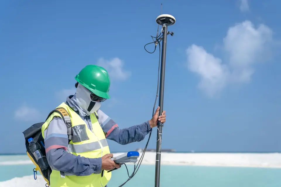
You do not need to repeat the survey to form your own view. With a GNSS RTK receiver or a total station and a short day in the field, the essentials can be checked.
1. Measure a few known points
Choose a set of points spread across the area, on firm, flat, open surfaces: roads, levelled platforms, slabs, corners of concrete structures. Avoid embankments, wall edges, vegetation and stockpiles, where a small horizontal error turns into a large height error. Measure them in the same reference system and with the same geoid model as the delivery. If the site already has setting-out stations or survey monuments, use them.
Your own measurement also has an error. GNSS RTK measures with an uncertainty of centimetres, larger in height than in position. A small difference at a single point proves nothing: what matters is the set as a whole.
2. Compare with the DTM
Extract the DTM elevation at each point (any GIS can do it) and calculate the difference from your measurement. From those differences, work out the mean error, the RMSE and the maximum error, and note where each point is. The pattern of the errors tells you as much as their size.
| What you see | What it usually indicates | First step |
|---|---|---|
| A similar difference at every point | Systematic shift (geoid, antenna, base) | Review both parties’ reference systems |
| Differences growing towards one end | Tilt or drift in the block | Ask for residuals and the GCP layout |
| One or two points far off | Poorly resolved area or a badly measured point | Repeat the measurement and review the area |
| Large errors only under vegetation | Insufficient ground classification or coverage | Ask for the ground point density in that area |
For the orthophoto, overlay known features from your own mapping or from the site (kerbs, manholes, building corners) and measure the horizontal shift.
3. Look at edges, overlaps and continuity
Many defects can be seen without measuring anything:
- A hillshade of the DTM reveals bumps that are misclassified vegetation, pits that make no sense and steps.
- In the overlaps between LiDAR strips or photogrammetric blocks, a step in the ground indicates that the strips are not properly adjusted to each other.
- At the edges of the area the geometry is usually weaker: check that the checkpoints reach there too.
- In the orthophoto, look for seamlines cutting through buildings or roads, duplicated features and distortion on bridges and eaves.
- Contour lines should be consistent with the DTM they come from, with no crossings or breaks.
A comparison with the IGN MDT05 is useful for detecting gross errors, such as a wrong UTM zone or geoid. It is not useful for assessing centimetre-level accuracy: its resolution, accuracy and date are different.
What to ask the supplier for if something does not add up
Before raising a complaint, rule out your own side: same datum, same UTM zone, same type of height, same antenna height and same units. Some discrepancies end there.
If the difference persists, send the supplier your points with coordinates, date, equipment and measurement method, the reference system you measured them in and the area or file where the problem appears. Then ask for:
- The full list of control points and checkpoints, with their residuals in X, Y and Z.
- The field observations for those points and the reference base used.
- An explanation of the difference and, where appropriate, a corrected product with a new control report.
What prevents most disputes is decided before the flight: the required accuracy, how it is expressed (RMSE or 95%), how many checkpoints there will be and who measures them. In our work, the accuracy for each project is agreed in the proposal and documented in the control report. If it is written down from the start, reviewing the delivery comes down to checking that it is met.
Frequently asked questions
How many checkpoints are needed?
It depends on the size of the area, its shape and the accuracy required. With three or four points the RMSE says little; many specifications start at around twenty, spread across the whole area and across the different types of ground. The number is best fixed in the specification or the proposal.
Can the same points be used for control and for checking?
No. A point that is used in the adjustment is no longer independent: its residual measures the fit, not the accuracy. If the report does not keep them apart, ask for it to do so.
What is the difference between precision and accuracy?
Precision is the repeatability of a measurement: points that always come out similar. Accuracy is how close the measurement is to the true value in the reference system. A model can be very precise and still be shifted as a whole by a few centimetres; that is why accuracy is checked with independent points. If your project needs a survey with documented control from the outset, our drone surveying service and our digital terrain model (DTM) page detail the deliverables, the formats and how accuracy is agreed.
Written by the fita team, drone mapping and surveying in Xàtiva (Valencia, Spain).